A mesh link can look fast in a one-hop test and still disappoint once traffic crosses several relay nodes. The reason is not simply “more distance”: each hop consumes additional airtime, and shared-radio backhaul can force nodes to take turns receiving and forwarding traffic, reducing usable throughput as the path grows. For anyone planning a Mesh Radio network, the real challenge is estimating how much capacity remains at the far end. Understanding airtime, contention, interference, link quality, and spatial reuse makes it easier to predict multi-hop performance and avoid designing around misleading single-hop speed figures.
The Airtime Cost Behind Every Relay
Receive, Then Forward: One Payload Uses the Channel Repeatedly
Consider a simple A → B → C path. Node A transmits a packet to B; B must receive that packet and then send it onward to C. If B uses a half-duplex Mesh Radio on the same wireless resource, reception and forwarding are not independent operations that can happen freely at the same instant. One application packet therefore occupies the medium once on A–B and again on B–C, even though the payload itself has not grown.
This distinction explains why PHY rate and usable throughput should never be treated as the same number. A radio may report a high negotiated data rate on both links, but the end-to-end flow still pays the airtime cost of every relay transmission. As more hops are added, the route spends a larger share of its available channel time moving already-received packets forward. For a Mesh Radio deployment, that repeated use of airtime is the first capacity cost to account for.
Contention and Protocol Overhead Consume the Remaining Capacity
Forwarding is only part of the airtime budget. Neighboring nodes that share a channel may also fall inside the same contention or interference domain, so one link has to wait while another is active. Channel-access procedures, acknowledgements, routing messages, inter-frame timing, and retransmissions consume additional time that does not appear as application payload.
The result is a gap between headline link speed and delivered data rate. Adding another Mesh Radio hop adds another transmission opportunity that has to be scheduled around the rest of the network, and it may also increase the control traffic needed to maintain the path. This is why multiplying a single-hop speed by the number of nodes tells an engineer almost nothing about end-to-end capacity. The finite resource is usable airtime, not the number printed beside the modulation rate.
The 50% Per-Hop Rule Is Useful—but Not Universal
Where the Half-Per-Hop Shortcut Makes Sense
The “half per hop” rule became popular because it captures an important worst-case behavior in single-radio or heavily shared-channel backhaul. When one relay receives traffic and then forwards it using the same constrained wireless resource, roughly twice as much channel time may be required to move the flow across two links. Under those conditions, a Mesh Radio path can lose a large portion of its usable throughput after only one additional relay.
A planning example such as 100 → 50 → 25 Mbps is therefore useful as a conservative stress test, but not as a guaranteed progression. It should prompt the designer to ask whether the application can tolerate severe relay overhead and contention, not imply that every third hop must deliver exactly one quarter of first-hop throughput.
Why a Linear Chain Can Follow a Different Throughput Curve
A better engineering question is: how many links must stay silent while one link transmits? In a simplified linear chain, each Mesh Radio may interfere mainly with nearby neighbors rather than with every node in the route. Packet-forwarding throughput can follow a 1/N relationship as hop count initially increases rather than repeated exponential halving.
Topology changes the contention pattern. A line of well-spaced relays is not equivalent to a dense mesh where several nodes can hear one another and defer transmissions. Two paths with the same hop count can therefore have different end-to-end capacity even when their nominal link rates are identical.
Spatial Reuse Changes What Happens on Longer Paths
Spatial reuse is the key reason longer paths do not always deteriorate according to a simple exponential curve. If two links are far enough apart that simultaneous transmissions do not materially interfere, they can reuse the same time or spectrum resource. A distant pair of Mesh Radio links may therefore transmit concurrently while adjacent links still have to take turns.
The practical implication is simple: hop count is only one input to throughput planning. Interference range, node spacing, frequency assignment, and scheduling determine how expensive each new relay actually becomes.
Throughput model
Useful for
Main assumption
~50% per-hop estimate
Conservative first-pass planning
Strong same-channel contention
Hop-sharing / 1/N model
Simple linear relay analysis
Limited concurrent transmissions
Spatial-reuse model
Longer, well-spaced paths
Distant links can transmit concurrently
Field measurement
Final deployment decisions
Real topology, RF conditions, and traffic
What Pushes Multi-Hop Throughput Lower in the Field
A Weak Link Can Slow the Entire Route
Real deployments rarely consist of identical links. One Mesh Radio hop may have lower SNR because of distance, partial obstruction, poor Fresnel-zone clearance, foliage, buildings, terrain, or node movement. Adaptive modulation can keep that link connected by shifting toward a more robust rate, but sending the same amount of data then requires more airtime. Every flow that crosses that slower hop inherits the resulting bottleneck.
This is the weakest-link effect in practical form. A four-hop route with three strong links and one marginal link can perform worse than a five-hop route built from stable, higher-rate links. The key metric is therefore not average signal quality across the mesh; it is the condition of the links that carry the important end-to-end traffic. For mobile Mesh Radio networks, the bottleneck can also move as nodes and obstructions change position.
Interference, Retries, and Traffic Concentration Compound the Loss
Interference converts usable airtime into wasted attempts. If packets collide or arrive corrupted, they must be retransmitted, which means the Mesh Radio network spends additional channel time delivering the same application data. Co-channel activity and hidden-node behavior can make this problem worse because transmitters may contend indirectly through a shared receiver even when they do not sense one another reliably.
Traffic aggregation adds a different kind of pressure. A relay close to a gateway or command point may need to forward several video feeds, telemetry streams, voice sessions, and control packets from downstream nodes. That relay can become the bottleneck even when each individual link is healthy. As a result, two routes with equal hop counts may deliver very different throughput because one carries heavier aggregated traffic or suffers more retries.
Design Choices That Keep More Capacity Available
Reduce Same-Channel Competition Before Adding More Hops
The first design priority is to avoid relay stages that the coverage problem does not require. Each additional Mesh Radio should be positioned to maintain a stable link without placing too many active relays inside the same contention area. Where the architecture allows it, separating interfering forwarding links across channel or frequency resources reduces the need for those links to wait on one another. Using two frequency channels for different forwarding links can substantially reduce interference compared with forcing every relay onto one shared frequency.
Traffic distribution matters too. A topology that sends every high-rate stream through one relay may create a local bottleneck before the rest of the network is heavily loaded. Route planning should therefore consider traffic concentration as well as hop count.
Use MIMO and Adaptive RF Features to Protect Per-Hop Efficiency
MIMO and adaptive RF functions help preserve per-hop efficiency when conditions permit. Spatial multiplexing can raise link capacity, while receive diversity and beamforming can improve robustness and signal quality. Adaptive modulation lets a Mesh Radio trade speed for reliability as RF conditions change, while intelligent frequency selection or frequency hopping can help avoid problematic spectrum.
QoS does not create bandwidth, but it can decide which traffic gets served first when capacity is constrained. Voice, control data, or mission-critical video may need priority over bulk transfers. These techniques cannot remove the basic airtime cost of relaying, but they can reduce avoidable losses.
Use Product Specifications as Planning Inputs, Not End-to-End Guarantees
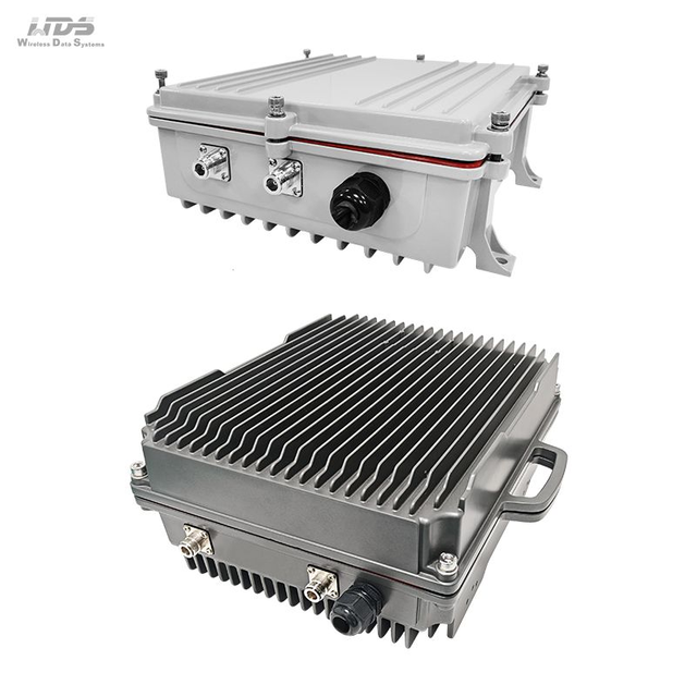
WDS’s MIMOmesh Backpack provides a practical example of a high-capacity Mesh Radio designed around MIMO, adaptive data rates, beamforming, and multi-hop routing. It supports receive diversity, TX/RX beamforming, spatial multiplexing, configurable channel bandwidths, adaptive data rates, QoS, intelligent frequency selection, adaptive frequency hopping, and dynamic multi-hop routing. Star, line, network, and hybrid operating modes provide additional flexibility for different network layouts.
The MIMOmesh Backpack supports 15+ hops for data, 10+ for voice, and 8+ for video, with total transmission-rate loss of less than 70% beyond three hops. Those figures are useful planning inputs, but they are not a substitute for testing a specific traffic mix and RF environment. The broader WDS portfolio includes broadband Mesh Radio and narrowband MESH options in handheld, airborne, backpack, outdoor, vehicular, and module-based form factors.
Plan Around End-to-End Throughput, Not Headline Link Speed
Work Backward From the Application
Start with the traffic the network must carry at the farthest useful point, not with peak single-hop speed. A Mesh Radio plan should account for the number and bitrate of video streams, voice and control traffic, telemetry, file transfers, acceptable latency and jitter, simultaneous users, and the maximum expected hop depth. Add headroom for routing overhead, retransmissions, and changing RF conditions instead of sizing the network to an ideal laboratory result.
The 50%-per-hop model can still be useful as a stress case. If the application fails even under a modest number of conservative reductions, the design needs more capacity, fewer shared hops, or a different channel strategy. After that first screen, use a topology-aware estimate based on the busiest path and the weakest likely link.
Test the Route at the Hop Depth You Will Actually Use
Final validation should reproduce the path the deployment will use. Measure the Mesh Radio network at one hop, two hops, three hops, and the intended maximum hop count while realistic traffic is active. Useful measurements include TCP/UDP end-to-end throughput, per-hop SNR and negotiated rate, packet loss, retransmissions, channel utilization, latency, jitter, and throughput while multiple application streams are running.
Repeat those measurements with realistic node positions, movement, obstacles, and interference rather than relying on a bench test with clean line of sight. A strong one-hop result only proves that the first link works well. For a multi-hop Mesh Radio system, the meaningful performance number is the usable throughput that remains at the required hop depth under the traffic and RF conditions the application will actually face.
Conclusion
Multi-hop throughput drops because every relay consumes airtime, while contention, interference, weaker links, retransmissions, and traffic concentration can reduce usable capacity further. The practical response is to design around end-to-end performance rather than single-hop peak speed, keeping relay links strong and limiting unnecessary channel competition. Shenzhen Sinosun Technology Co., Ltd. offers Mesh Radio solutions such as the MIMOmesh Backpack series, combining MIMO, beamforming, spatial multiplexing, adaptive data rates, and frequency-hopping capabilities to support more efficient multi-hop communication. Careful topology planning and realistic field testing remain essential for achieving dependable throughput.
FAQ
Q: Does mesh network speed decrease with every hop?
A: Yes. Each relay must receive and forward traffic, consuming additional airtime. The actual reduction depends on channel sharing, interference, link quality, traffic load, and radio architecture.
Q: Does throughput always drop by 50% per mesh hop?
A: No. A 50% reduction is mainly a planning rule for shared-radio, same-channel conditions. Spatial reuse, separate channels, multi-radio designs, and topology can produce different results.
Q: What affects Mesh Radio throughput across multiple hops?
A: Key factors include half-duplex forwarding, channel contention, SNR, modulation rate, retransmissions, interference, node spacing, traffic aggregation, frequency allocation, and whether distant links can transmit simultaneously.
Q: How many mesh hops can a network use efficiently?
A: There is no universal limit. The practical hop count depends on required application bandwidth, RF conditions, network topology, traffic volume, latency targets, and measured end-to-end throughput.
Q: Can multiple radios or channels reduce multi-hop throughput loss?
A: Yes. Using separate radios or frequency channels can reduce repeated same-channel contention, allowing more forwarding activity to occur concurrently and preserving greater end-to-end capacity across the mesh.